08.16
08.16
 Apoeyz

10 Langkah Setting Router sederhana menggunakan MikroTik
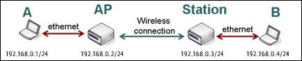
Contoh Kasus :PC CLient — > Switch –> Router —> Internet
IP PUBLIC : x.y.z.pub/29
DNS : x.y.z.dns1 dan x.y.z.dns2
Gateway : x.y.z.gw
IP address LOCAL ROUTER : 192.168.100.1/24
IP address Client : 192.168.100.2/24
Catatan : Sesuaikan Hardware, IP Address, DNS, Gateway dengan yang anda miliki
Hardware :
Router : RouterBoard 1000 (Mikrotik v3,19 Stable)

Mikrotik RB1000
Switch : D-Link DES-3026 Ethernet Switch

D-Link DES-3026 Ethernet Switch

Powerbook G4
Setting ROUTER
1. Ganti default password Mikrotik
[admin@titik.org] > /user set admin password=whatever
2. Rename ethernet name :
[admin@titik.org] > /interface print
Flags: D – dynamic, X – disabled, R – running, S – slave
# NAME TYPE MTU
0 R ether1 ether 1500
1 ether2 ether 1500
2 ether3 ether 1500
3 R ether4 ether 1500
[admin@titik.org] > /interface set ether1 name=IP-LOCAL
[admin@titik.org] > /interface set ether4 name=IP-PUBLIC
[admin@titik.org] > /interface print
Flags: D – dynamic, X – disabled, R – running, S – slave
# NAME TYPE MTU
0 R IP-LOCAL ether 1500
1 ether2 ether 1500
2 ether3 ether 1500
3 R IP-PUBLIC ether 1500
3. Setting IP Address
[admin@titik.org] > /ip address add address=x.y.z.pub/29 interface=IP-PUBLIC
[admin@titik.org] > /ip address add address=192.168.100.1/24 interface=IP-LOCAL
[admin@titik.org] > /ip address print
Flags: X – disabled, I – invalid, D – dynamic
# ADDRESS NETWORK BROADCAST INTERFACE
0 x.y.z.pub/29 x.y.z.168 x.y.z.175 IP-PUBLIC
1 192.168.100.1/24 192.168.100.0 192.168.100.255 IP-LOCAL
4. Setting Gateway
[admin@titik.org] > /ip route print
Flags: X – disabled, A – active, D – dynamic, C – connect, S – static, r – rip, b – bgp, o – ospf, m – mme,
B – blackhole, U – unreachable, P – prohibit
# DST-ADDRESS PREF-SRC GATEWAY-STATE GATEWAY DISTANCE INTERFACE
0 ADC x.y.z.168/29 x.y.z.pub 0 IP-PUBLIC
1 ADC 192.168.100.0/24 192.168.100.1 0 IP-LOCAL
[admin@titik.org] > /ip route add dst-address=0.0.0.0/0 gateway=x.y.z.gw
[admin@titik.org] > /ip route print
Flags: X – disabled, A – active, D – dynamic, C – connect, S – static, r – rip, b – bgp, o – ospf, m – mme,
B – blackhole, U – unreachable, P – prohibit
# DST-ADDRESS PREF-SRC GATEWAY-STATE GATEWAY DISTANCE INTERFACE
0 A S 0.0.0.0/0 reachable x.y.z.gw 1 IP-PUBLIC
0 ADC x.y.z.168/29 x.y.z.pub 0 IP-PUBLIC
1 ADC 192.168.100.0/24 192.168.100.1 0 IP-LOCAL
5. Test Ping Gateway
[admin@titik.org] > /ping x.y.z.gw
x.y.z.gw 64 byte ping: ttl=64 time=1 ms
x.y.z.gw 64 byte ping: ttl=64 time=1 ms
x.y.z.gw 64 byte ping: ttl=64 time=1 ms
3 packets transmitted, 3 packets received, 0% packet loss
round-trip min/avg/max = 1/1.0/1 ms
6. Setting DNS
[admin@titik.org] > /ip dns print
primary-dns: 0.0.0.0
secondary-dns: 0.0.0.0
allow-remote-requests: no
max-udp-packet-size: 512
cache-size: 2048KiB
cache-max-ttl: 1w
cache-used: 4KiB
[admin@titik.org] > /ip dns set primary-dns=x.y.z.dns1 secondary-dns=x.y.z.dns2 allow-remote-requests=yes
[admin@titik.org] > /ip dns print
primary-dns: x.y.z.dns1
secondary-dns: x.y.z.dns2
allow-remote-requests: yes
max-udp-packet-size: 512
cache-size: 2048KiB
cache-max-ttl: 1w
cache-used: 10KiB
7. Test Koneksi Ke Internet (contoh ping yahoo.com)
[admin@titik.org] > /ping yahoo.com
206.190.60.37 64 byte ping: ttl=48 time=300 ms
206.190.60.37 64 byte ping: ttl=48 time=299 ms
206.190.60.37 64 byte ping: ttl=48 time=316 ms
206.190.60.37 64 byte ping: ttl=48 time=316 ms
206.190.60.37 64 byte ping: ttl=48 time=311 ms
5 packets transmitted, 5 packets received, 0% packet loss
round-trip min/avg/max = 299/308.4/316 ms
8. Setingg NAT (Network address Translation)
[admin@titik.org] > /ip firewall nat print
Flags: X – disabled, I – invalid, D – dynamic
[admin@titik.org] > /ip firewall nat add chain=srcnat src-address=192.168.100.0/24 action=src-nat to-addresses=z.y.z.pub
[admin@titik.org] > /ip firewall nat print
Flags: X – disabled, I – invalid, D – dynamic
0 chain=srcnat action=src-nat to-addresses=x.y.z.pub src-address=192.168.100.0/24
Setting PC CLIENT
9. Setting IP Address client

Setting IP Adress Client
Subnet : 255.255.255.0
Gateway : 192.168.100.1
DNS : 192.168.100.1
10. Test koneksi dengan ping ke Router, Gateway, DNS dan yahoo.com
- Ping Router
Perk1z:~ herman$ ping 192.168.100.1
PING 192.168.100.1 (192.168.100.1): 56 data bytes
64 bytes from 192.168.100.1: icmp_seq=0 ttl=64 time=0.360 ms
64 bytes from 192.168.100.1: icmp_seq=1 ttl=64 time=0.257 ms
64 bytes from 192.168.100.1: icmp_seq=2 ttl=64 time=0.254 ms
^C
— 192.168.100.1 ping statistics —
3 packets transmitted, 3 packets received, 0% packet loss
round-trip min/avg/max/stddev = 0.254/0.290/0.360/0.049 ms
- Ping Gateway
perk1z:~ herman$ ping x.y.z.gw
PING x.y.z.gw (x.y.z.gw): 56 data bytes
64 bytes from x.y.z.gw: icmp_seq=0 ttl=63 time=1.813 ms
64 bytes from x.y.z.gw: icmp_seq=1 ttl=63 time=1.538 ms
64 bytes from x.y.z.gw: icmp_seq=2 ttl=63 time=1.368 ms
^C
— x.y.z.gw ping statistics —
3 packets transmitted, 3 packets received, 0% packet loss
round-trip min/avg/max/stddev = 1.368/1.573/1.813/0.183 ms
- Ping DNS
perk1z:~ herman$ ping x.y.z.dns1
PING x.y.z.dns1 (x.y.z.dns1): 56 data bytes
64 bytes from x.y.z.dns1: icmp_seq=0 ttl=62 time=1.437 ms
64 bytes from x.y.z.dns1: icmp_seq=1 ttl=62 time=3.945 ms
64 bytes from x.y.z.dns1: icmp_seq=2 ttl=62 time=1.576 ms
^C
— x.y.z.dns1 ping statistics —
3 packets transmitted, 3 packets received, 0% packet loss
round-trip min/avg/max/stddev = 1.437/2.319/3.945/1.151 ms
- Ping Yahoo
perk1z:~ herman$ ping yahoo.com
PING yahoo.com (206.190.60.37): 56 data bytes
64 bytes from 206.190.60.37: icmp_seq=0 ttl=47 time=303.308 ms
64 bytes from 206.190.60.37: icmp_seq=1 ttl=47 time=309.105 ms
64 bytes from 206.190.60.37: icmp_seq=2 ttl=47 time=306.238 ms
^C
— yahoo.com ping statistics —
3 packets transmitted, 3 packets received, 0% packet loss
round-trip min/avg/max/stddev = 303.308/306.217/309.105/2.367 ms
Selamat mencoba dan Semoga bermanfaat :D


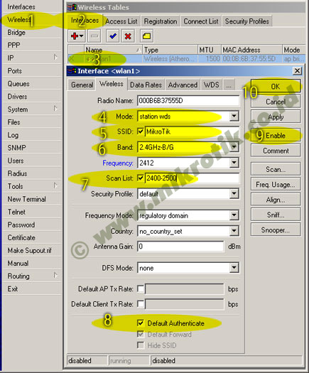
 4. Selanjutnya adalah setting wireless interface. Kliklah pada menu Wireless (1), pilihlah tab interface (2) lalu double click pada nama interface wireless yang akan digunakan (3). Pilihlah mode AP-bridge (4), tentukanlah ssid (5), band 2.4GHz-B/G (6), dan frekuensi yang akan digunakan (7). Jangan lupa mengaktifkan default authenticated (8) dan default forward (9). Lalu aktifkankanlah interface wireless (10) dan klik OK (11).
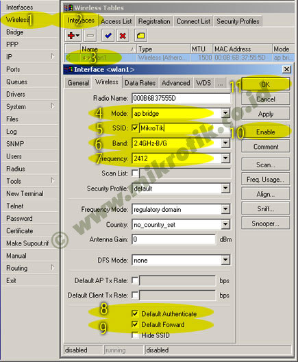
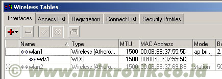
 6. Langkah selanjutnya adalah menambahkan virtual interface WDS. Tambahkan interface WDS baru seperti pada gambar, lalu pilihlah interface wireless yang kita gunakan untuk WDS ini. Lalu tekan OK.
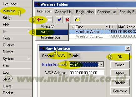 7. Jika WDS telah ditambahkan, maka akan tampak interface WDS baru seperti pada gambar di bawah.
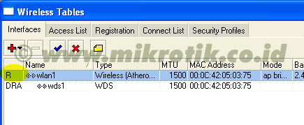
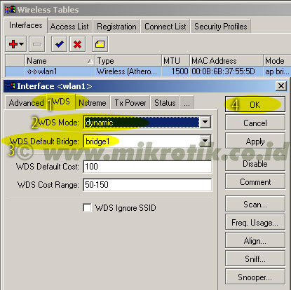